An end-grain face is assembled from crosscut elements. The finished pattern depends on the strip widths in the first panel, the crosscut thickness, the order of the slices, and any flips or offsets used in the second glue-up. Those values must be planned together.
A quick map of Endgrain Studio
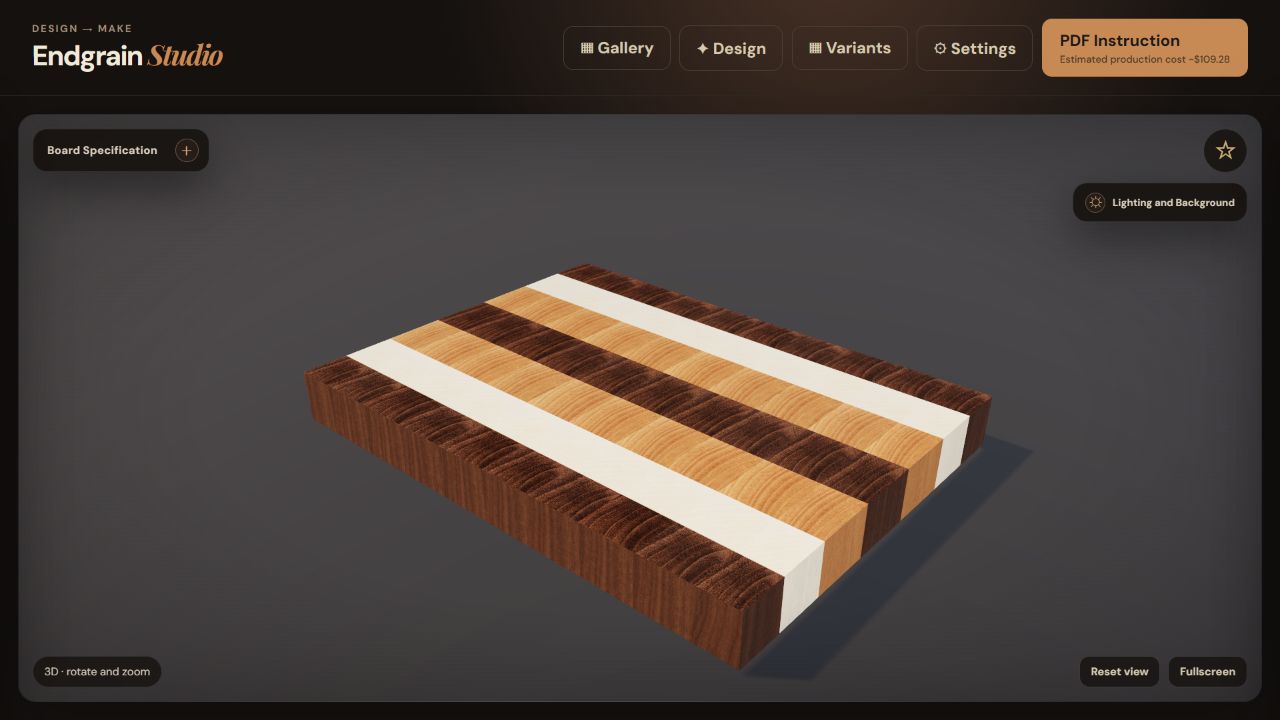
The board stays in the center. Design controls open on the left; generated variants open on the right.
 123
123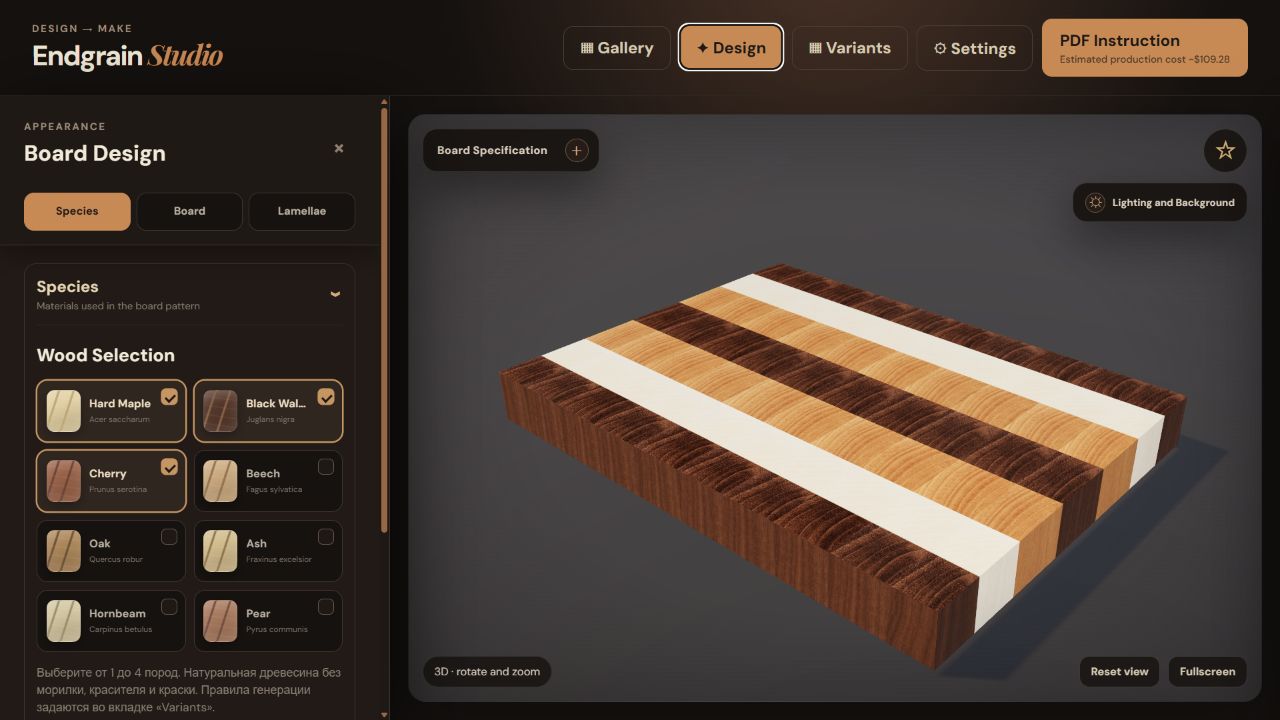 123
123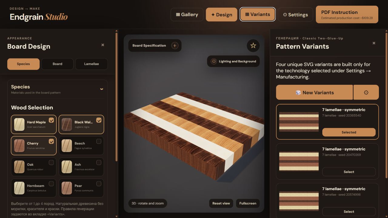 123
1231. Write down the constraints
Before choosing a pattern, record the intended use and the limits of the workshop.
- Use: general prep, carving, serving, or a specific workstation.
- Available space: counter depth, storage, sink clearance, and comfortable lifting.
- Handling: target weight, handholds, feet, and whether both faces should remain usable.
- Maintenance: how easily the owner can clean, dry, and re-oil the board.
- Workshop limits: planer or drum-sander capacity, saw setup, clamp reach, and stock on hand.
Use the list to reject designs that are too large, too heavy, or incompatible with the available machinery and clamps.
2. Choose finished dimensions first
Set the finished width, depth, and thickness before laying out the pattern. The pattern must fill this exact boundary, while the rough assembly must be larger.
Width and depth
Check the counter, sink, and storage space. Leave enough clearance to lift the board and clean around it. If it must fit a shelf or drawer, do not match the opening exactly.
Thickness
Thickness affects weight, stiffness, edge profiles, and flattening allowance. Check the resulting weight and the capacity of the flattening setup before increasing it.
Keep finished and rough dimensions separate. Flattening, trimming, kerf, and profile machining consume material. A finished 40 mm board cannot be planned from a rough assembly that is also exactly 40 mm.
3. Design a pattern that can be made
Most classic end-grain patterns begin with a first panel made from parallel strips. That panel is crosscut into slices, the slices are rotated so end grain faces upward, and they are arranged for a second glue-up. The final pattern is therefore controlled by both the strip recipe and the slice sequence.
- Draw the finished face as a grid of physical elements.
- Identify which visible cells originate from the same first-panel strip.
- Set strip widths and slice thicknesses that your tools can reproduce safely and consistently.
- Decide whether alternating slices are flipped, shifted, or kept in the same orientation.
- Check the pattern at the actual finished boundary—not only as an endlessly repeating tile.
Do not scale the drawing to force a fit; that changes every strip width. Calculate the repeat at its real size, then decide whether to trim the edge modules or change the recipe.
4. Choose the species
Choose material for the intended use and verify that the stock is dry, sound, and suitable for the project. Colour contrast alone is not enough.
- Use one main species, one contrasting species, and an accent only if it adds something to the pattern.
- Vary strip width instead of giving every species equal area.
- Preview the wood under neutral light; oil will change its colour and contrast.
- Measure moisture content and inspect the stock before fixing the dimensions.
- Check compatibility before combining species with different movement or machining behaviour.
5. Translate the face design into a process
Record the first-panel strip list, panel length, crosscut count, slice thickness, kerf, second glue-up order, and finishing allowance.
Account for kerf and trim
Every rip and crosscut removes material. Add kerf per cut, not per finished piece, and distinguish reusable offcuts from unavoidable waste. Leave explicit margins for jointing, flattening, squaring, and final edge cleanup.
Check tool capacity
Make sure each intermediate assembly—not just the final board—fits the planned machinery and clamping setup. Define an alternative flattening method before the glue-up if the board will exceed planer capacity. Never put end grain through equipment in a way that conflicts with the tool manufacturer's guidance or safe workshop practice.
6. Add edge details after the core geometry works
Corner radii, roundovers, chamfers, handholds, feet, and juice grooves should support how the board is used. Add them after the primary pattern and dimensions are stable because they consume edge area and may alter usable surface, thickness, or two-sided use.
- Keep a groove clear of the outer profile and corner radii.
- Check groove width and depth against available cutter geometry and board thickness.
- Choose top and bottom edge treatments independently when they serve different purposes.
- Review how a profile cuts through the pattern at every edge and corner.
7. Review the complete board before cutting
Compare the dimensioned top view and 3D view with the stock and cut summary.
- Confirm finished dimensions, weight implications, and storage fit.
- Trace every visible pattern element back to a strip and slice.
- Verify the species list and available stock sizes.
- Recalculate kerf, flattening, trim, and profile allowances.
- Check intermediate panel sizes, clamp strategy, and tool capacity.
- Print the sequence and ask whether another maker could follow your assumptions.
Workshop note: Endgrain Studio provides preliminary planning output, not a certified manufacturing instruction. Validate dimensions, tooling, material suitability, glue, finish, and safe procedures for your own workshop.
Endgrain Studio
Build and check the design
Enter the pattern and finished dimensions, inspect the 3D board, then review the material calculation and manufacturing sequence.
Open Studio ↗